|
Autor:
|
Kommentar:
|
Ad
22.03.10 11:02
|
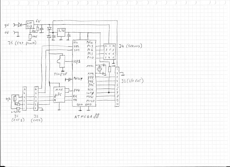
The x-tal freq. is 14745600 Hz which is ideal for the Baudrate of 921600 Baud.
The servo connector doubles as connector for the Sharp sensors (inputs as ADC). Beware of the pinning though. Also 6V is a bit high for the Sharps, therefore I recommend using a Si series diode. Any type of 3.3V regulator will do, I used one in a TO-92 case. I used a 38kHz IR sensor, it works but it should be a 36kHz.
Purists will be appalled by the direct connection between the MAX485 and the ATMega, if you are afraid that you'll kill the ATMega, add a series resistor in the RX line. The servo voltage can be lowered (use Schottky diodes), to as low as 4.8V. Below 5.2V the atmega will always be powered from the TX connector.
|
| |
|

")